
SELECTED WORK

Real projects, details under NDA.

Every engagement we take on is covered by a non-disclosure agreement. The case studies below describe the engineering problem and what we built — without naming the client. Full specifications are available on request once an NDA is in place.

CLIENT NAMES WITHHELD BY DEFAULT
8-Layer UAV Flight Controller - PixHawk DS12 StandardUAV / FLIGHT CONTROL

8-Layer UAV Flight Controller - PixHawk DS12 Standard

The Challenge

A stackable flight controller platform needed to fit a high-pin-count BGA processor, a secondary co-processor, and fully redundant sensor paths into a compact, mezzanine-style 3-board architecture — without compromising signal integrity or serviceability.

What we did

An 8-layer board built around an STM32H7-class BGA processor paired with an STM32F103 co-processor, with redundant IMU and sensor paths for fault tolerance. Designed to Pixhawk DS12 mechanical and connector standards, and built DFM-ready for direct submission to JLCPCB.

Layers
8
MCU
STM32H7 + F103
Sensors
Redundant IMU
Form
Pixhawk DS12
DETAILS UNDER NDA · FULL SPECS AVAILABLE ON REQUEST
6-Layer UAV Flight Controller — PixHawk DS10 StandardUAV / FLIGHT CONTROL

6-Layer UAV Flight Controller — PixHawk DS10 Standard

The Challenge

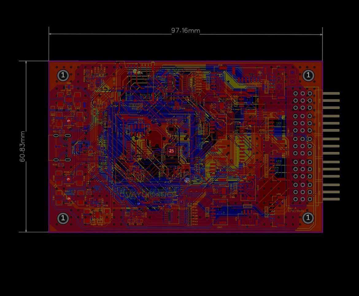
The client needed a UAV flight controller for an industrial/agricultural drone platform, built to the Pixhawk DS10 mechanical and connector standard. The design required a single-board layout supporting CAN, telemetry, GPS, and safety interfaces, along with onboard data logging — all within a compact form factor suitable for integration into an existing airframe.

What we did

We designed a 6-layer flight controller around an STM32H7-series MCU in LQFP package, paired with onboard SD card storage for flight data logging. The board breaks out dual CAN buses, dual telemetry connectors, dual GPS inputs with a dedicated GPS+safety interface, I2C and ADC headers for peripheral sensors, and a USB-C debug/programming interface — all routed to Pixhawk DS10 connector and mechanical standards. The first revision was fabricated, assembled, and bench-verified for full functionality before sign-off.

Layers
6
MCU
STM32H7
Features
CAN, I2C, GPS, SD card
DETAILS UNDER NDA · FULL SPECS AVAILABLE ON REQUEST
Smart Lead-Acid BMS with Cloud MonitoringBATTERY MANAGEMENT / EV-MOBILITY

Smart Lead-Acid BMS with Cloud Monitoring

The Challenge

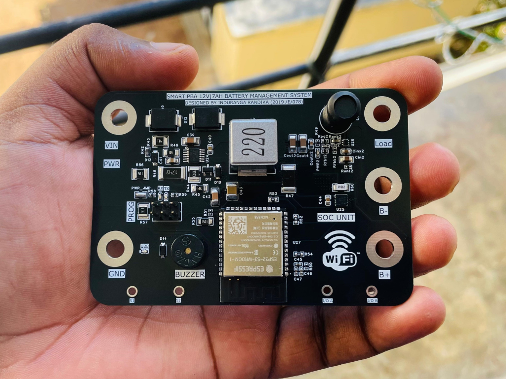
Built independently to explore accurate state-of-charge estimation for 12V/7Ah lead-acid batteries in e-mobility applications - a class of battery where simple voltage-based SOC estimation is notoriously inaccurate due to voltage sag under load and chemistry-dependent discharge curves.

What we did

Designed an ESP32-S3-based smart battery management system combining a dedicated charge controller IC with a 14-bit coulomb counter for accurate SOC tracking, going beyond simple voltage estimation. The board manages the full 3-stage charging profile for lead-acid batteries (bulk, absorption, float) and streams battery state data to a cloud backend over Wi-Fi. A companion mobile application, also developed in-house, gives the end user real-time visibility into battery health, charge state, and history.

Layers
4
MCU
ESP32 S3 N8R8
SOC Resolution
14 Bit
Connectivity
WIFI
DETAILS UNDER NDA · FULL SPECS AVAILABLE ON REQUEST
Multi-Protocol Cellular IoT GatewayIOT / INDUSTRIAL MONITORING

Multi-Protocol Cellular IoT Gateway

The Challenge

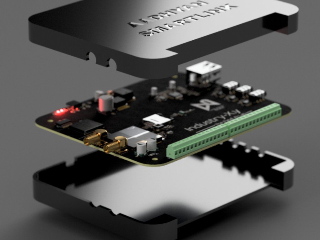
The client needed a field-deployable industrial monitoring gateway capable of ingesting sensor data across multiple protocols — UART, I2C, SPI, and analog — and relaying it over both cellular and wired Ethernet using Modbus TCP/IP. The device also needed to be powered and programmed entirely through a single USB-C connection, with reliable cellular connectivity in areas with weak signal coverage.

What we did

We designed a compact PCB built around an ESP32-S3 main controller, integrating a SIM7600E cellular module with dual gain antennas for redundant signal reception, alongside a W5500 Ethernet controller for wired Modbus TCP/IP communication. The board exposes UART, I2C, SPI, and analog input headers to support a wide range of third-party sensors, with a micro-SIM slot for cellular data. Power and firmware programming are both handled over a single USB-C port, simplifying field deployment and updates. The design was carried through to a custom two-piece enclosure, milled with mounting features for the antenna connectors and external I/O.

Layers
4
MCU
ESP32 S3
Network
W5500
Cellular
SIM7600E
DETAILS UNDER NDA · FULL SPECS AVAILABLE ON REQUEST
NeatLink - Long-Range LoRa Home Automation Hub (In Development)IOT / HOME AUTOMATION · R&D PROJECT

NeatLink - Long-Range LoRa Home Automation Hub (In Development)

The Challenge

Standard Wi-Fi based home automation nodes are limited by router range - typically no more than 100m before connectivity becomes unreliable. For multi-story buildings or larger properties in the Sri Lankan market, this range ceiling makes whole-building automation impractical without multiple routers or mesh extenders. We wanted to explore a different architecture: keep individual nodes simple and long-range, and put the complexity in a single intermediary hub.

What we did

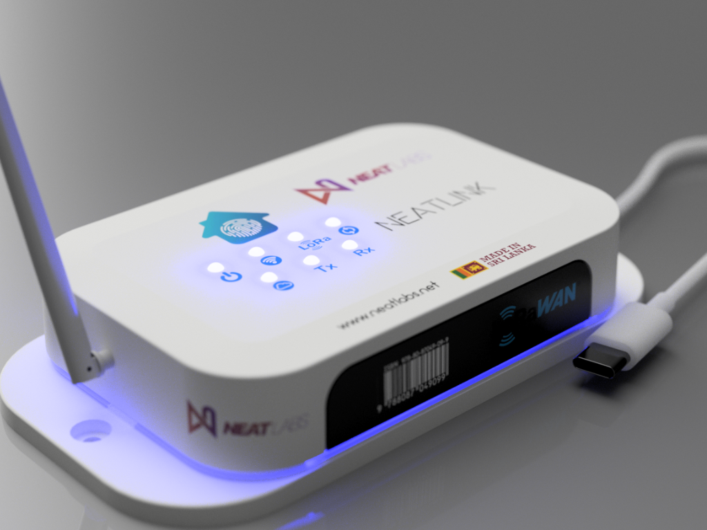
NeatLink is an OEM home automation hub concept that sits between the home Wi-Fi router and a network of long-range LoRa nodes, rather than connecting nodes directly to the router. Nodes communicate with the hub over LoRa, well beyond typical Wi-Fi range, and the hub handles the single Wi-Fi uplink to the cloud — removing the range limitation from every individual node. The current build includes LoRa Tx/Rx status indicators, Wi-Fi/WAN connectivity, and a fingerprint-style status display on the enclosure. The product is still in active development; this case study reflects our current build, not a finished, field-deployed product.

Layers
4
Wireless
ESP32, LoRa
Range
12Km (LOS)
DETAILS UNDER NDA · FULL SPECS AVAILABLE ON REQUEST
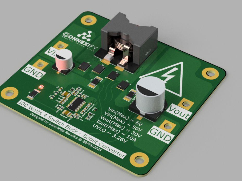
300W Synchronous Buck-Boost ConverterPOWER ELECTRONICS · PERSONAL VENTURE (CONNEXIFY)

300W Synchronous Buck-Boost Converter

The Challenge

Designed for Connexify, an independent hardware venture, to solve a common power-supply problem: maintaining a stable output voltage when the input source varies both above and below the target — a scenario where a simple buck or boost converter alone isn't sufficient. The design needed to handle a wide 6–50V input range, deliver a fixed 30V output, and support up to 10A of load, all while keeping conversion efficiency high.

What we did

Designed a synchronous 4-switch buck-boost converter capable of holding a 30V output across a 6–50V input range, with a maximum load of 10A. The 4-switch synchronous topology was chosen specifically for efficiency — avoiding the losses of diode-based rectification used in simpler buck-boost designs. The board includes proper UVLO (under-voltage lockout) protection and was laid out with clear high-current and high-voltage isolation zones, reflecting the safety margins needed at this power level.

Layers
4
Input Range
6V – 50V
Output Voltage
30V (fixed)
Max Output Current
10A
DETAILS UNDER NDA · FULL SPECS AVAILABLE ON REQUEST
WORK WITH US

Have a comparable project?

If your project shape resembles any of the above — or differs in interesting ways — we'd like to hear about it.